Interfacing an ESP32 to an MCP23017 GPIO expander
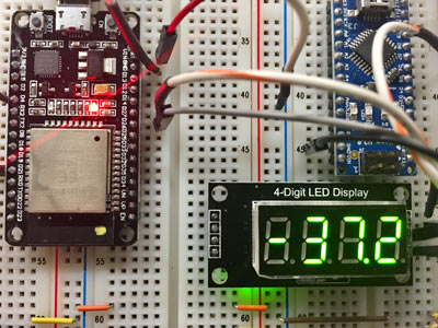
While the ESP32 sports a number of GPIO pins, not all are broken out on every board, meaning that sometimes a GPIO expander is necessary. This project is a simple design to test interfacing the ESP32 to an MCP23017 via the I2C interface.
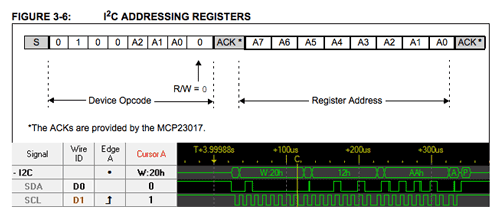
There are so many tutorials on the MCP23017 that I won’t delve in depth into how it works, but I’ll point out a few features of the custom MCP23017 component that I’m developing as part of this demonstration project. If you need to get up-to-speed developing applications using I2C within the ESP-IDF environment, this tutorial from Luca Dentella is excellent and concise.
MCP23017 component API
All of my custom components are on github. You can clone or download the MCP23017 component there. Once you’ve installed the MCP23017 component in the components directory of your project, you can follow the preliminaries here to start working with it.
Preliminaries
You will need to include the header file for the component in your project and specify the I2C pins that correspond to your hardware design:
#include "mcp23017.h"

#define I2C_SDA	23	// GPIO_NUM_23
#define I2C_SCL 22	// GPIO_NUM_22
In addition, you will also probably want to create a reference to the mcp23017_t structure on a global scope:
mcp23017_t mcp;Initialization
Before we can use the component, we have to initialize it. The API provides a function for this purpose mcp23017_err_t mcp23017_init(mcp23017_t *mcp).
mcp.i2c_addr = MCP23017_DEFAULT_ADDR;
mcp.port = I2C_NUM_1;
mcp.sda_pin = I2C_SDA;
mcp.scl_pin = I2C_SCL;

mcp.sda_pullup_en = GPIO_PULLUP_ENABLE;
mcp.scl_pullup_en = GPIO_PULLUP_ENABLE;

esp_err_t ret = mcp23017_init(&mcp);
ESP_ERROR_CHECK(ret);
We simply populate the mcp23017_t struct with the data need to initialize the bus and pass its address to the initialization function, checking the return value to make sure everything initialized without error.
Reading and writing registers
The API provides two functions mcp23017_write_register and mcp23017_read_register to write and read MCP23017 registers respectively. To write to a register, you provide the address of the mcp23017_t struct, a register, a group and the value you are writing. All of the device registers are paired into A and B groups. So when you use one of these two functions you provide a register name and the specific group you’re addressing. For example to set all of the pins in group A to output mode:
mcp23017_write_register(mcp, MCP23017_IODIR, GPIOA, 0x00);Reading is a little different because the return value of mcp23017_read_register like its write counterpart is still an error/status code. Therefore, we pass the address of the variable into which we’d like to read an eight-bit value.
uint8_t current_value;
mcp23017_err_t ret = mcp23017_read_register(mcp, reg, group, ¤t_value);If you want to check out the complete demonstration project, you can find it on github.