Using the Raspberry Pi to communicate over the I2C bus using C
I recently wrote about using the excellent bcm2835 library to communicate with peripheral devices over the SPI bus using C. In this post, I’ll talk about using the same library to communicate over the I2C bus. Nothing particularly fancy, but you’ll need to pay careful attention to the datasheet of the device we’re using. TheTSL2561 is a sophisticated little light sensor that has a very high dynamic range and is available on a breakout board from Adafruit. I’m not going to delve into the hookup of this device as you can take a look at the Adafruit tutorial for that. Note that we’re not going to use their library. (Well, I borrowed a bunch of their #define statements for device constants.)
TSL2561 functions
The {% asset_link TSL2561.pdf “TSL2561” %} has two analog-digitial (ADC) channels. Channel 0 responds to broad spectrum visible and IR wavelengths, whereas channel 1 responds to IR only. For most applications, you’ll address channel 0.
TSL2561 I2C interface
The {% asset_link TSL2561.pdf “TSL2561 datasheet” %} is a little confusing because the device family also uses the SMBus and the format differences get lost between the text and the figures. The bottom line with the TSL2561 is that if you want to read a register, you write to the COMMAND register, then read a byte. It’s important to understand how the COMMAND register is configured so that you can read and write to the appropriate registers. Here is the COMMAND register format:
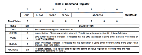
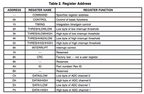
Note that the CMD bit (7) must always be set. For ordinary read/write operations, we’ll leave the CLEAR, WORD, and BLOCK bits unset. The remaining 3:0 ADDRESS bits specify the register that we are addressing. The registers are found in Table 2, reproduced below:
Editorial note: don’t be tempted to figure out the bits and encode the command yourself. Always use symbolic references for bit positions. By using symbolic references to bit positions and register addresses you will make your code much more readable. If you configure the COMMAND register as 0x8A, then I have convert the hex to binary and refer back to the datasheet to understand what you’re trying to do. On the other hand, if you configure the command as TSL2561_COMMAND_BIT | TSL2561_REGISTER_ID then I can immediately see you are addressing the ID register.
Sample code
I will go through a working example section by section and provide a github link at the end where you can grab the entire code.
char buf[3];
uint8_t err;

printf("Running ... \n");

if (!bcm2835_init())
{
  printf("bcm2835_init failed. Are you running as root??\n");
  return 1;
}

 if (!bcm2835_i2c_begin())
 {
    printf("bcm2835_i2c_begin failed. Are you running as root??\n");
    return 1;
 }
In our main function, we begin by declaring variables we’ll need later and call two important functions on the bcm2835 library: bcm2835_init() and bcm2835_i2c_begin(). The former sets up our library and from the documentation:
Initialises the library by opening /dev/mem (if you are root) or /dev/gpiomem (if you are not) and getting pointers to the internal memory for BCM 2835 device registers. You must call this (successfully) before calling any other functions in this library (except bcm2835_set_debug). If bcm2835_init() fails by returning 0, calling any other function may result in crashes or other failures. If bcm2835_init() succeeds but you are not running as root, then only gpio operations are permitted, and calling any other functions may result in crashes or other failures.
The latter starts I2C operations by forcing P1-03 (SDA) and P1-05 (SCL) to their alternate function ALT0 thereby enabling them for I2C use. After all I2C operations are done, the program should call bcm2835_i2c_end() to return those pins to their regular functions. Note that for the purposes of this demonstration, I check all of the return codes and printf an informative messages. In a robust application we would want to deal with this in a more fault-tolerant way.
Next we’ll set up some features of the bus:
bcm2835_i2c_setSlaveAddress(TSL2561_ADDR_FLOAT);
bcm2835_i2c_setClockDivider(BCM2835_I2C_CLOCK_DIVIDER_150);
After that, we ready to work with the device. Let’s begin with a simple reading of the ID register. To simplify matters, we’ll create a reusable function readRegister():
uint8_t readRegister(uint8_t reg, uint8_t *fail) {
	uint8_t b[2];
	b[0] = TSL2561_COMMAND_BIT | reg;
	int err = bcm2835_i2c_write(b,1);
	if( err != BCM2835_I2C_REASON_OK ) {
		printf("Unable to write command register %02x\n",err);
		*fail = 1; return 1;
	}
	err = bcm2835_i2c_read(b,1);
	if( err != BCM2835_I2C_REASON_OK ) {
		printf("Unable to read last command response %02x\n",err);
		*fail = 1; return 1;
	}
	*fail = 0;
	return b[0];
}
When we want to read a register, we just need to pass the address of the register and a pointer to a uint8_t in which we’ll return the status (0 for success and 1 for failure.) Why don’t we just return a status? It’s because we’re already returning the results of the read. When the caller passes the address of a status variable, we can fill it, and the caller just looks at it afterwards.
In lines 2-3, we are building the COMMAND “register” value to send. Because the datasheet says to set the CMD bit, we do that. Then we logical OR the address into bits 3:0. Then we write the COMMAND register to the device and read a byte. Remember that we’ve already set the hardware address previously.
So calling readRegister() to read the hardware ID will look like:
//	Read the ID register

uint8_t id = readRegister(TSL2561_REGISTER_ID, &err);
if( err == 1) {
	printf("Check ID register failed.\n"); return 1;
}
printf("The ID is %02x.\n",id);
We can do something similar to read another register, such as the TIMING register 0x01h:
//	Read the timing register

uint8_t tr = readRegister(TSL2561_REGISTER_TIMING,&err);
if(err == 1) {
	printf("Check timing register failed.\n");
	return 1;
}
printf("The timing register is %02x.\n",tr);
On my device I get a value of 0x03 which is the default power-up value according to the datasheet.
Now we need to get down to the business of writing to a register. Since we have to explicitly turn on the ADC, we’ll have to write to a control register. A generic writeRegister() should help with this. Again our design uses a pointer to a uint8_t to return the status. We don’t have to do this because a write operation has no useful return, but for API symmetry, I wrote the function the same way.
void writeRegister(uint8_t reg, uint8_t val, uint8_t *fail) {
	uint8_t b[2];
	b[0] = TSL2561_COMMAND_BIT | reg;
	int err = bcm2835_i2c_write(b,1);
	if( err != BCM2835_I2C_REASON_OK ) {
		printf("Unable to write command register %02x\n",err);
		*fail = 1; return;
	}
	b[0] = val;
	err = bcm2835_i2c_write(b,1);
	if( err != BCM2835_I2C_REASON_OK ) {
		printf("Unable to write command register %02x\n",err);
		*fail = 1; return;
	}
	err = bcm2835_i2c_read(b,1);
	if( err != BCM2835_I2C_REASON_OK ) {
		printf("Unable to read following write command register %02x\n",err);
		*fail = 1; return;
	}
	*fail = 0;
	return;
}
Writing to a register is similar to reading except that after addressing the register, we have to send it some data in a subsequent write operation. Following those two operations, we have an obligatory read and move on.
Lines 3-9 address the COMMAND register as we did before. Lines 9-14 write the caller’s specified value to the address specified in the preceding COMMAND call. Then a read that we can disregard and return to the caller.
Turn on the ADC
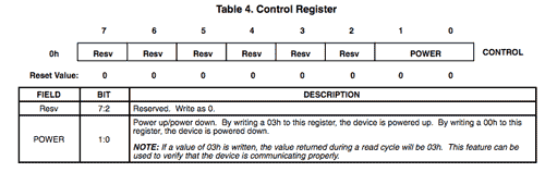
Turning on the ADC couldn’t be easier; we just need to address the CONTROL register 0x00. The CONTROL register documentation tells us that we simply need to set the POWER bits (1:0) to 0x03 to power up the device or 0x00 to power it down.
Doing that in code using our generic write function couldn’t be simpler:
writeRegister(TSL2561_REGISTER_TIMING,TSL2561_CONTROL_POWERON, &err );
if( err == 1 ) {
	printf("Unable to power on the TSL2561.\n"); return 1;
}
Take a broad spectrum reading on Channel 0
Now we come to the reason we started working with the device, to take a light measurement. We’re going to focus on the visible + IR channel (Channel 0) but the same principles apply to either channel. We’re just going to do sequential reads from the two channel 0 registers and assemble the result:
uint8_t LSB0 = readRegister(TSL2561_REGISTER_CHAN0_LOW, &err);
if( err == 1 ) {
	printf("Unable to read LSB0\n"); return 1;
}
uint8_t MSB0 = readRegister(TSL2561_REGISTER_CHAN0_HIGH, &err);
if( err == 1 ) {
	printf("Unable to read MSB0\n"); return 1;
}
int lux = (int)(MSB0 << 8) | (int)LSB0;
printf("Light value is %d lux.\n",lux);
There’s a lot more that we could cover, both about the operation of the device and about using I2C on the Raspberry Pi in general, but this should be enough to get you started with luminosity measurement using the TSL2561 or in beginning to code your own I2C interfaces using the BCM2835 library on the Raspberry Pi.