Implementing ADC using Raspberry Pi and MCP3008
Several years ago I wrote about adding analog-to-digital capabilities to the Raspberry Pi. At that time, I used an ATtinyx61 series MCU to provide ADC capabilities, communicating with the RPi via an I2C interface. In retrospect it was much more complicated than necessary. What follows is an attempt to re-do that project using an MCP3008, a 10 bit ADC that communicates on the SPI bus.
MCP3008 device
The MCP3008 is an 8-channel 10-bit ADC with an SPI interface^[Datasheet can be found here.]. It has a 4 channel cousin, the MCP3004 that has similar operating characteristics. The device is capable of performing single-ended or differential measurements. For the purposes of this write-up, we’ll only concern ourselves with single-ended measurement. A few pertinent details about the MCP3008:
- It is capable of conversion rates of around 200 kilosamples per second.
- It operates on SPI modes 0,0 or 1,1^[The SPI bus can operate in different ways depending on the clock polarity and phase and how the data relates to clock transitions. “Mode 0,0” means that the clock polarity is 0 and its phase is 0 whereas “mode 1,1” means that the clock polarity and phase are both 1.]
If you have done any work with SPI, you’ll know that there are 4 signals. MOSI stands for “master out, slave in” whereas MISO stands for “master in, slave out”. The two other signals are the clock which provides a time standard for the digital transaction and the SS (slave select), also called CE (chip enable) or CS (chip select.)
SPI communication in 8-bit read/write frames
In this example, we are going to use an SPI library to communicate with the MCP3008 in 8-bit frames, so the pertinent section of the datasheet is on page 21, section 6.1 Using the MCP3004/MCP3008 with Microcontroller (MCU) SPI Ports. The Figure 6-1 (reproduced below) shows how we will go about communicating with the device over the SPI bus.
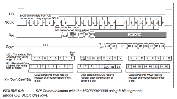
From the communication diagram above, we get an excellent overview of the entire transaction. First, we must drop CS to initiate the transaction. With the CS low, we begin clocking in and out data. Figure 6-1 shows that we must clock in a single start bit (0x01) followed by mode and channel select bits. Table 5-2 shows the configuration bits that we must clock-in to return an ADC reading.
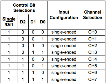
For example, if we wish to make a single-ended reading on channel 0, we must clock in the bits 1000. Note from figure 6-1, we must shift the bits by 4 binary places, so that for a single-ended reading from channel 0, we would clock in 0b1000000 or 0x80.
Software implementation
I chose to implement this in C rather than Python this time. There are a handful of libraries for the BCM2835. I used the bcm2835 library which is excellent. It is low-level enough that I can what’s going on, but not completely “bare metal” programming. You can find out more about the spi module of this library.
I will start with the code section-by-section then provide a link to the entire source code. First, of course, you’ll need to install the library. You can find a version-agnostic install script here. I used it; it works.
First, we’ll include a couple libraries that we need, and set up three constants. The first is the 0b00000001 that we need to transfer as the start bit. The second is the end bits 0b00000000 that we clock in to the MCP3008 so that we can clock out 8 bits of the ADC value. Finally, since I set up my test circuit to measure on channel 0, I just define a constant for that.
#include <stdio.h>
#include <bcm2835.h>

uint8_t start = 0x01;
uint8_t end = 0x00;
uint8_t chan = 0x00;
Next I declare my function prototypes. Just C business as usual.
int readADC(uint8_t chan);
float volts_adc(int adc);
In the body of main, I start by testing whether I can initiate the SPI interface on the Pi:
if (!bcm2835_init())
{
  printf("bcm2835_init failed. Are you running as root??\n");
  return 1;
}

if (!bcm2835_spi_begin())
{
  printf("bcm2835_spi_begin failed. Are you running as root??\n");
  return 1;
}
If we pass those tests, we’re ready to go. Let’s set up the interface.
bcm2835_spi_setBitOrder(BCM2835_SPI_BIT_ORDER_MSBFIRST);      // The default
bcm2835_spi_setDataMode(BCM2835_SPI_MODE0);                   // The default
bcm2835_spi_setClockDivider(BCM2835_SPI_CLOCK_DIVIDER_65536); // The default
bcm2835_spi_chipSelect(BCM2835_SPI_CS0);                      // The default
bcm2835_spi_setChipSelectPolarity(BCM2835_SPI_CS0, LOW);      // the default
To read the ADC value, we have to prepare the bytes that we’ll clock in first. All of that is done in a function readADC.
int readADC(uint8_t chan){
  char buf[] = {start, (0x08|chan)<<4,end};
  char readBuf[3];
  bcm2835_spi_transfernb(buf,readBuf,3);
  return ((int)readBuf[1] & 0x03) << 8 | (int) readBuf[2];
}
It looks like there’s a lot going on here, but basically we are performing bit manipulations to get the input bits in the right order and the same for the output bits. First we declare an output buffer buf[] whose contents are three bytes. The first is the start bit 0b00000001, followed by the mode selections bytes, and terminated by a junk byte so that we can finish clocking out the resulting data. How do we interpret the value of (0x08|chan)<<4? Start from the inside of the parenthesis. 0x08 is 0b00001000 where the 1 bit here represents the selection of single-ended mode on the ADC. We logical OR that with the channel that we want to read. Finally, outside the parenthesis, we shift it over by 4 bits so these bits are in the upper nibble. Remember we have to clock in the data MSB first?
Next we declare an input buffer readBuf[3] to hold the data we’re reading in. Then we perform a 3 byte transfer. Now, what do we do with the results? Ouch. Well, remember we reading in 3 bytes. The first lines up with our start bit, so it’s junk and we’ll just ignore readBuf[0]. What about the next byte readBuf[1]? From Figure 6 of the datasheet, you can see that we only care about the 2 lower bits of the first byte which will become the upper two bits of the 10-bit ADC result. First we logical AND those with 0x03 (0b00000011) to get rid of anything above the first two bits. Then we shift it over by 8 bits, so that when we logical OR it with the lower 8 bits in readBuf[2] it coheres into a single 16 bit int. The casts just keep everything in 16 bits along the way.
Real life
So, does the software work? We can test it by applying a logical probe instrument and find out. I used an Intronix logic analyzer to watch the conversion. Here’s the result:
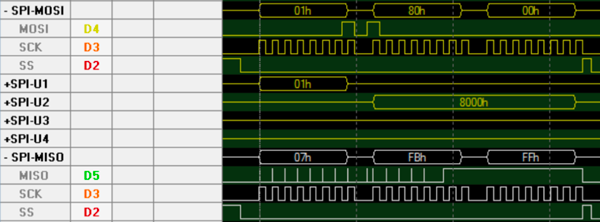
Compare the logic analyzer image to the datasheet. Looks similar! On the MISO line, we can ignore the first byte 0x07. With the second byte, 0xFB (0b11111011) we only care about the bottom two bits (11). In the third byte, we use all 8 bits. Putting those 10 bits together we have 0b1111111111 or 0x3FF, 1023 decimal. That’s the largest number we can express in 10 bits. That’s because I tied channel 0 to the 3.3v out of the Raspberry Pi. Now we can calculate the voltage. Using the reference of 3.3v, the ADC value of 1023 represents 3.3v and we can compute an arbitrary value using a function:
float volts_adc(int adc) {
  return (float)adc*3.3f/1023.0f;
}
And that’s it - a working example of reading the MCP3008 using C on the Raspberry Pi. If you’d like the entire code for the example application, you can find the gist here..