A quick word on ATtiny 1-series interrupts
The Atmel AVR 8-bit microcontrollers have always been a favourite for tinkering; and the massive popularity of the Arduino based on the ATmega 168 and 328 MCUs introduced a lot of hobbyists to this series. The companion ATtiny series from Atmel were the poor stepchildren of the ATmega controllers to an extent - useful for small projects but often quite limited. However, the acquisition of Atmel by Microchip Technology in 2016 ushered in a new series of MCUs bearing the same moniker of ATtiny, but much more capable and innovative. They have been around for a while now, but many hobbyists are just beginning to poke around with these new capable MCUs.
Some of the positives of the tinyAVR 1-series are:
- The introduction of the UPDI programming interface - moving away from ICSP is a major step forward. Not only does this redue the pin count required for programming from 4 to 1.
- Event System: The Event System allows for direct communication between peripherals without involving the CPU. This can lead to more efficient use of resources and faster response times in applications that require real-time processing or precise timing.
- Configurable Custom Logic (CCL): The CCL enables the creation of simple logic functions directly in hardware, reducing the need for external components and allowing for more compact and power-efficient designs.
Since, I’m just beginning to look into these MCUs, this post and likely others to follow are just to document some of the features and works in case learning about them is helpful to others.
Prerequisites
Since I’m on macOS and do not own a dedicated Microchip/Atmel branded UPDI programmer, using Microchip Studio with, say an Atmel ICE programmer is not in the cards. For the moment, I’m just working in the Arduino IDE. Not my favourite at all, but with some effort you can get the job done. To program these controllers you do need to set up both the software and hardware environment first.
Hardware setup
You will need a UPDI programmer. There are several options here:
- Buy a dedicated UPDI programmer. There are several on the market through Tindie and elsewhere. I have not evaluated them at all; but some seem to be quite capable, including the ability to mass-program devices without a computer.
- Convert an Arduino (Uno, Nano, etc.) to a dedicated programmer. This is what I did, using a 5V Nano. It’s a slight overkill but it works. Two modifications are necessary to make it work:
- Add a 10 uF capacitor from RESET to GND
- Add a 4K7 Ω resistor from D6 to the UPDI pin.
- Upload
jtag2updisketch to the Arduino
- Convert a USB to serial adapter to a UPDI and use SerialUPDI to program the target.
Software setup
In the Arduino environment, you will need to add the megaTinyCore board library. The installation documentation is straightforward; but it involves a step which requires loading a library.json file from this URL: http://drazzy.com/package_drazzy.com_index.json. Unfortunately at the time of this writing the SSL certificate on this site has expired and Arduino IDE refused to load the library. When you are reading this, it may be fixed; but there is a workaround:
- Navigate to the URL and when the browser complains about the security risk, just accept it and download the json file.
- Provide the file URL to the Board Manager in the Arduino preferences. In my case it was:
file:////Users/alan/Documents/dev/tinyMegaCore.json - Then install the library in Board Manager.
A few caveats:
- You need to select the programmer in the
Toolsmenu. It isjtag2updi. - The Upload button does not work. You need to use
Sketch>Upload Using Programmer. - You may see the error avrdude: jtagmkII_initialize(): Cannot locate “flash” and “boot” memories in description. Apparently it is inconsequential. It certainly seems so.
Interrupts, finally
Now, finally the actual subject of the post - interrupts on the tinyAVR 1-series. I’m only concerned with pin interrupts here. They are easy to use and configure but there are a few things to be aware of:
- Any pin can have an external interrupt
- All interrupts on a port have a single vector. It is up to the developer to distinguish between the pins that could have generated the interrupt. For example
PORTA_PORT_vectcovers all of the interrupts on thePORTApins. - The developer is responsible for clearing the interrupt flag in the interrupt service routine.
- The Arduino function
attachInterrupt()can be used, but it is not recommended. There are several reasons for this; but chiefly it imposes significant overhead.
The simple project I’m describing here uses one of those microwave presence detectors that you can find everywhere on AliExpress:
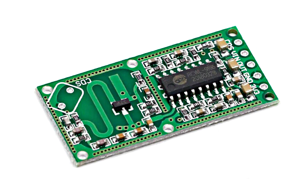
I’ve wired this up with an ATtiny 1614 on an SMD to DIP adapter board, with the microwave module connected to PA5 and an indicator LED to PA6. When presence is detected, the code should toggle the LED. Simple.
Set up interrupt
To set up the interrupt, we will just designate PA5 as an input pin and enable a rising signal interrupt on it:
void setup() {
    // Interrupt on PA5
    PORTA.DIRCLR = PIN5_bm;
    PORTA.PIN5CTRL = PORT_ISC_RISING_gc;

    // enable global interrupts
    sei();
}
Don’t forget to enable global interrupts with sei().
Interrupt service routine
As mentioned, all of the pins in a port are capable of using external interrupts, but they share a single vector. Our ISR needs to distinguish which pin generated the interrupt, do its work as quickly as possible and reset the interrupt flag, not necessarily in that order.
volatile bool didReceiveRadarPulse = false;

ISR(PORTA_PORT_vect) {
    // reset the PORTA.INTFLAGS - necessary on this series
    uint8_t portAFlags = PORTA.INTFLAGS;
    PORTA.INTFLAGS = portAFlags;
    if (portAFlags & PIN5_bm) {
        // Handle the interrupt for PA5
        didReceiveRadarPulse = true;
    }
}
The trick of reading the flags and writing the same value back to them works because of a hardware feature of this register:
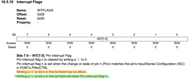
So, we just read the value so we can use it to test whether our PA5 interrupt was triggered and then immediately write the value back to reset it. We could also just do the pin toggle in the ISR, but since we’re leaving the door open to doing more sophisticated things with this skeletal code, we will set a boolean didReceiveRadarPulse to true and then act on that in the loop().
Toggle a pin
In other MCUs toggling a pin often meant keeping track of the state yourself. Interestingly, the tinyAVR 1-series has a register just for toggling an output pin. So we can just PORTA.OUTTGL = PIN6_bm and it’s done!
Complete code
Here’s the full working code for ATtiny 1614.
/*

Test interrupts on ATtiny 1614

*/
#include <Arduino.h>
#include <avr/io.h>
#include <avr/interrupt.h>

volatile bool didReceiveRadarPulse = false;

ISR(PORTA_PORT_vect) {
    // reset the PORTA.INTFLAGS - necessary on this series
    uint8_t portAFlags = PORTA.INTFLAGS;
    PORTA.INTFLAGS = portAFlags;
    if (portAFlags & PIN5_bm) {
        // Handle the interrupt for PA5
        didReceiveRadarPulse = true;
    }
}

void setup() {
    PORTA.DIRSET = PIN6_bm;  // simple toggle
    PORTA.OUTCLR = PIN6_bm;  // turn off
    // Interrupt on PA5
    PORTA.DIRCLR = PIN5_bm;
    PORTA.PIN5CTRL = PORT_ISC_RISING_gc;
    // enable global interrupts
    sei();
}

// the loop routine runs over and over again forever:
void loop() {
    if (didReceiveRadarPulse) {
        PORTA.OUTTGL = PIN6_bm;
        didReceiveRadarPulse = false;  // reset our radar pulse flag
    }
}
If you have any difficulties, I can try to help. See my contact page.
References
- jtag2updi project - the sketch you will need if you want to repurpose an Arduino as a UPDI programmer.
- megaTinyCore - the Arduino core for these boards
- Introduction to the tinyAVR 1-series chips - from Microchip
- ATtiny 1614 datasheet - the official word on the target used in this post